Assembly Guide
Contents
Wiring the Raspberry Pi
This section is still being written. Contribute?
Raspberry Pi is ESD-sensitive. Take all necessary precautions, and only perform work at ESD-safe workspaces.
Step 1. Test Raspberry Pi for DOAness
We recommend that you test the Raspberry Pi outside of the Roomba, before installation. If you have received a defective or dead-on-arrival part (especially if you bought used), it’s best to figure that out now.
Instructions:
- If there’s anything plugged into the Raspberry Pi, unplug it, including the MicroSD card.
- Using a 5vDC USB-A to USB Micro-B cable, connect the Raspberry Pi’s DC input to a standard USB wall wart or computer. If connected to a computer, the computer will only deliver power, no data. The Raspberry Pi can be run off of as small as a 5W AC adapter.
- As soon as the power cord is connected, the power LED should illuminate on the board and the processor should start to get slightly warm. If none of the components get warm and the LED does not light up, double-check that your wall wart is outputting 5vDC and that your USB-A to USB Micro-B cable is not damaged or broken. If it still doesn’t work, you may have gotten a defective or dead-on-arrival part. Stop now.
- If nothing starts smoking and the Raspberry Pi seems to be working properly, good! Unplug it for now.
Step 2. Getting and Writing a Raspbian Image
Raspbian is a distribution of Linux based on Debian. It has a very Ubuntu-like feel, but doesn’t run a lot of background applications, since processor cycles and RAM are at a premium.
Instructions:
- Go to the Raspbian download page and download the appropriate version of the software for your computer. You can either use the Raspberry Pi imager, which works kind of like the Windows Media Creation Tool, or you can just get the operating system image as an .iso disc image file and use a tool like NOOBS to write it.
- Insert the MicroSD card into the MicroSD to SD adapter, then insert the SD card into your computer’s SD card reader. If your SD card is new, you might be prompted to “initialize” or “format” the card. Just ignore this for now.
- If you’re using the Raspberry Pi imaging tool, you can run it now, selecting the SD card as the installation target. If you’re using another piece of software to write a disc image to the SD card (like NOOBS), consult that developer’s documentation. The goal is to write the OS image to the SD Card, which we can then use.
- If you are using a Mac and you are prompted whether you’d like to use the storage medium as a Time Machine drive, select Decide Later (NOT Don’t Use!), since this doesn’t make any other changes to the disk. Windows users need not worry about this.
- Once your tool of choice has completed the write, eject the disk safely, then remove the SD card from your SD card reader. Remove the MicroSD card from the adapter.
Step 3. Test Raspberry Pi for Bootability
Now that you have a Raspbian image loaded onto your SD card, we can make sure that your Raspberry Pi is functional and that it has networking capabilities.
Instructions:
- Insert the SD card from Step 2 into your Raspberry Pi’s MicroSD card slot.
- While the power cord is still detached from your Raspberry Pi, connect your HDMI cable to the Raspberry Pi and the other end to a monitor, and connect your USB keyboard and mouse.
- Now, plug the power back into your Raspberry Pi. It should automatically start booting up. If everything’s hunky-dory, you should see the boot sequence on the monitor. If you don’t see any output on the display after a few minutes, make sure your HDMI cable is securely connected and that your monitor is working (plugged in with the right input selected). If your monitor is fine, you might have a defective or dead-on-arrival Raspberry Pi.
- If the boot is successful, you should see options to configure your Raspberry Pi. If you don’t see these options, you may have a defective Raspberry Pi or a bad disk image. You can try to rewrite the disk image to the SD card, then reattempt Step 3.
- Configure your Raspberry Pi according to your preferences. There’s nothing too particular here.
- Once you’re presented with the desktop, click on the networking icon in the top-right corner. If you see that there are available networks, great! Now, you can shut down your Raspberry Pi, since we won’t need it to be on for a while. If you don’t see any networks, use another device to see if there are any WiFi b/g/n networks around. If not, you might not be able to test this yet. If so, you might have a defective wireless chipset on your Raspberry Pi. Regardless, shut down your Raspberry Pi through the operating system.
Step 4. Configure Wiring for Testing
Instructions:
- Get your jumper wires ready. We’ll mostly use Female-to-Female (F-F) jumpers, but we’ll also need some sacrificial F-M (M for Male) jumpers whose male end we’ll lop off and strip about 6-8mm of insulation from.
- Connect a red F-F jumper wire to pin 2 and a black F-F jumper wire to pin 25 of the GPIO headers. This provides +5vDC and floating ground to our motor driver.
- Connect a sacrificial F-M jumper wire (any color) to pin 3 and connect the other end to a 3-wide lever nut. These will be used to detect collisions from the limit switches.
- Connect another four F-F jumper wires (any color) to pins 13, 15, 16, and 18. These will be used to control the motor driver.
- Connect your momentary pushbutton to pin 5 using a sacrificial F-M jumper wire whose male end was soldered onto the common switch lead. Optionally, cover the solder joint with heat shrink tubing. Using a length of wire with bare ends (like primary wire), solder one end to the normally-open switch lead and attach the other end to pin 14.
- Connect a LED lamp to pin 11 using a F-F jumper wire to the positive end of the lamp and a F-F jumper wire to pin 9 for common.
- Connect another 3-wide lever nut to another length of wire with bare ends, and connect the other end of the wire to the black wire on pin 6. This, in conjunction with the wire going to pin 3, will give our Roomba collision detection. The other spaces on the 4-wide lever nuts will be taken with leads for the three limit switches.
- You don’t need to use any jumper wire for your speaker. Instead, use a 3.5mm audio cable to connect it to the Raspberry Pi’s built-in audio out (typically colored green).
Your Raspberry Pi should look like this. Don’t worry about the battery packs or the motor driver.

In summary, you should have jumper wires connected to pins 2, 3, 5, 6, 9, 11, 13, 14, 15, 16, 18, and 25.
- Pin 2 provides +5vDC
- Pin 3 is for collision detection and leads to a 3-wide lever nut
- Pin 5 is for the button
- Pins 6, 9, 14, and 25 are the floating common ground
- Pin 11 is for the LED lamp
- Pin 13 is blank and will be used for the motor driver
- Pin 15 is blank and will be used for the motor driver
- Pin 16 is blank and will be used for the motor driver
- Pin 18 is blank and will be used for the motor driver
- The 3.5mm out is for standard line-level audio output
Step 5. Test Wiring
If you have multimeter, you can test your wiring. If not, don’t worry about this part. Just double-check your work from Step 4.
Instructions:
- Power on the Raspberry Pi. You don’t need to have any peripherals connected.
- Test the connection from pin 2 to pin 6. It should read 5v. If it doesn’t, something’s wrong.
- Test the connection from pin 1 to pin 6. It should read 3.3v. If it doesn’t, the 3.3v rail is not working.
- Test the impedance from pin 1 to pin 6, 9, 14, and 25 using a low voltage, like 9v, 5v, or 3v. If the impedance is not reasonably low (it should be measured in milli-Ohms, that’s how low), something’s wrong (burnt out trace?).
- If all of the voltages are correct and the impedence between all of the ground pins is low, then you should be good to go!
Wiring the Motor Driver
This section is still being written. Contribute?
The motor driver is ESD-sensitive. Take all necessary precautions, and only perform work at ESD-safe workspaces.
Step 1. Wire the Motor Driver to the Raspberry Pi
Instructions:
- Locate the jumper wire coming off of the Raspberry Pi from pin 2 and connect it to the motor driver’s +5vDC pin.
- Locate the jumper wire coming off of the Raspberry Pi from pin 25 and connect it to the motor driver’s ground pin. Depending on your exact build of motor driver board (some come with a pin and a terminal for ground, others only provide the terminal), you might need to twist it into the ground from the +14/+18vDC battery pack.
- Locate the jumper wire coming off of the Raspberry Pi from pin 13 and connect it to the motor driver’s IN 1 pin.
- Locate the jumper wire coming off of the Raspberry Pi from pin 15 and connect it to the motor driver’s IN 2 pin.
- Locate the jumper wire coming off of the Raspberry Pi from pin 16 and connect it to the motor driver’s IN 3 pin.
- Locate the jumper wire coming off of the Raspberry Pi from pin 18 and connect it to the motor driver’s IN 4 pin.
- Get a male XT90 pigtail/lead and connect the positive wire to the VCC input and the ground to the ground input. You might need to twist it into the same wire as the lead from pin 25 on the Raspberry Pi. DO NOT CONNECT THE BATTERY PACK YET!
- Get a black length of wire and connect it to the OUT 2 terminal on the motor driver. Put some electrical tape on the other end for now.
- Get a black length of wire and connect it to the OUT 4 terminal on the motor driver. Put some electrical tape on the other end for now.
- Get a red length of wire and connect it to the OUT 1 terminal on the motor driver. Put some electrical tape on the other end for now.
- Get a red length of wire and connect it to the OUT 3 terminal on the motor driver. Put some electrical tape on the other end for now.
Double-check all of your wiring before continuing!
Step 2. Removing Motors from the Roomba
The Roomba comes with two motors, which run at a maximum of 18vDC. These motors can be removed easily and are direct-drive DC with an integrated gearbox. The Roomba’s motors are enclosed in a protective shell and are not ESD-sensitive.
Instructions:
- Flip your Roomba over so the wheels are point up.
- If still present, remove the brush assemblies and dustpan.
- As shown in the graphic below, remove these three screws. This will loosen the wheel assembly.
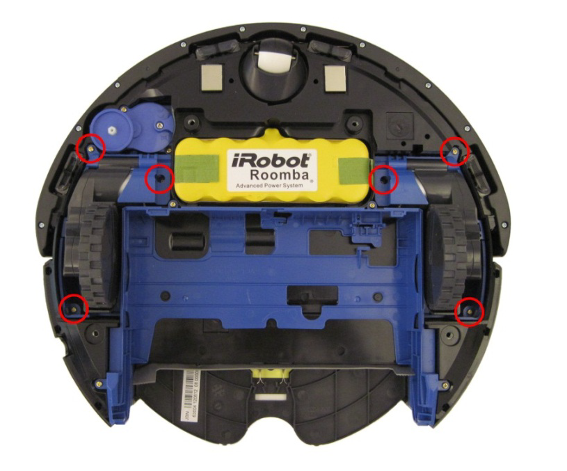
- Wiggle and lift each motor assembly straight out. Remove both the left and right wheel assembly. As you remove each, mark whether it belonged to the left- or right-side of the robot.
If you can’t figure out how to get the motors out, try harder. Your Roomba might be slightly different, depending on the model and year. I’m not going to help you if you’re a crackhead and addicted to crystal meth and have brain damage, tho.
Step 3. Wire the Motor Driver to the Motors
Your Roomba’s motors will run at whatever voltage your battery outputs at. Of note is that the polarity on one of the wheels needs to be reversed for both to move forwards relative to the robot. We are doing this polarity reversal in software, not by the hardware connection.
Instructions:
- Solder on another red wire to the red wire that corresponds to pin A on the wheel assembly’s PCB. We need to use this terminal to drive the motor. Do the same thing for the other motor assembly.
- Solder another black wire to the black wire that corresponds to pin B on the wheel assembly’s PCB. We need to use this terminal to drive the motor. Do the same thing for the other motor assembly.
- For your left motor, solder the other end of the red wire that you just attached to the motor to the OUT 1 wire from the motor driver. This, along with the next three wires, should be about 8 inches long to accomodate the pathing from the wheel-well to the computers.
- For your left motor, solder the other end of the black wire that you just attached to the motor to the OUT 2 wire from the motor driver.
- For your right motor, solder the other end of the red wire that you just attached to the motor to the OUT 3 wire from the motor driver.
- For your right motor, solder the other end of the black wire that you just attached to the motor to the OUT 4 wire from the motor driver.
- You can ignore the 5V, ENC, WD, and GND pins on the wheel PCB - these are connected to hall effect sensors that can detect if the robot has been picked up, but we don’t use them here.
Installing Components into the Roomba
This section is still being written. Contribute?
Overview
Your Roomba is now ready to have components shoved into it. This process is not pretty, and it’s probably going to change depending on your particular Roomba and what components you have.
We anticipate that the easiest ways to route the wiring is as follows:
- In the dustpan, mount the motor driver’s battery and stack the power bank on top of or underneath this. These components are liable to be the most difficult components to manage.
- In the remains of the brush motor assembly cavity, mount the speaker to one side.
- In the space that remains, mount the Raspberry Pi. From its central location, it should reach all of the locations in the device.
- Remove the old battery. In the remains of the old battery cavity, mount the motor driver. Its central location makes it good for wiring the motors.
- Remove the outer casing of the robot until you get access to the front bumper sensors (there are two), then lop off the connector to the existing sensor array and solder your own leads onto [colors unknown :(] wires. These leads will go to the 3-wide lever nut for collision detection.
Step 1. Mounting the Battery Packs
Instructions:
- Remove the existing dustpan by pressing on the button on the rear of the robot and pulling straight back.
2. Optionally, use a cleaning wipe to clean the large surfaces of the inside of the dustpan. Later, it will allow the battery packs to be adhesively mounted. 2. Remove the filter and discard - we no longer need it, since the robot has no more succ. 3. Remove the top lid to the dustpan and either cleanly remove it or just snap it off - we no longer need it, and it’s taking up valuable space that we need to route wiring. 4. Using a small amount of industrial-strength Velcro (if possible, avoid using the chicken-shit consumer-grade stuff, the adhesive fails too easily when heated), attach the 5vDC USB battery bank to the bottom of the dustpan. Align the bank so that the output port faces towards the front of the robot. 5. Depending on the shape of your battery bank, you might be able to attach the motor driver battery pack to the top of the USB battery bank. If your USB power bank is round, then you’ll probably need to mount your motor driver battery pack next to the USB power bank. Using some industrial-strength Velcro, attach the battery pack to the dustpan. Align the battery pack so that the pigtail faces the front of the robot. 6. Prepare the rest of the underside of the robot by removing the four screws holding the bottom protective plate on. All four screws are captive. 7. Remove the single screw holding the sweeper brush in, then pull the brush straight up and out. The brush is friction-mounted with a screw, so you might need to pull kind of hard. 8. Pull the entire bottom protective plate out. 7. Remove the brush assembly by removing the four screws holding it into place, then slide it straight up. You may need to wiggle it slightly. All screws holding the brush assembly are captive.
Optionally, you can drill two holes beside each battery pack, then use a zip-tie to cinch it down and secure it better to the dustpan. Be careful to not overtighten the zip-ties, especially on the motor driver’s battery pack. Be careful when cutting the zip-ties to not puncture any of the battery packs.
If or when you need to remove the battery packs, do not just pull on the battery pack - this can cause it to rupture and catch fire. Instead, slowly twist clockwise and counter-clockwise, back and forth, as you gently pull on the battery pack. The hook-and-loop fasteners will slowly let go; just be patient.
Step 2. Opening the Roomba to Gain Access to the Collision Switches
This is perhaps one of the most involved substeps. This will take a large chunk of your time to do right. If you want to “cheat” (it’s okay), you can use a power drill to remove some material from just behind the bumper, then shove a couple of limit switches in and wire them in. However, using the built-in switch array will provide much more accurate and reliable switch actuation, since the parts are actually designed for each other.
Instructions:
- The dustpan and brush assemblies should both already be removed.
- Remove the old battery pack by lifting it out using the two plastic tabs and disconnecting the pigtail, if your robot used a pigtail connector. Some models, like the 560, have a pogo connector instead.
- On the bottom of the robot, around the bumper, there are 10-12 screws (depending on your model) on the bottom of the front bumper plate. Unscrew all of them, then remove the arc-shaped bumper by wiggling it straight out. These screws are not designed to be captive, so remove the entire way.
- The bumper plate will get snagged on a set of wires, which provide the basic lighthouse sensing capabilities. We will not use them, so if you want, you can just cut these wires. Alternatively, you can unscrew the two screws holding the sensor from the front of the bumper to remove it. You can then remove the bumper’s outer surface from the entire robot.
- Turn the Roomba so it’s facing up again. Using a screwdriver, iFixit Jimmy, or just your fingers, lift up the silver or gray decorative cover. This plate is held in with plastic clips all around. You might need to pull quite hard to release all of the clips.
- When all of the clips have been freed, lift the silver/gray plate up and off of the robot. You might need to wiggle it off of the handle.
- Now that the top cover has been removed, you should see 11 screws, one of which has a smaller head (probably at the bottom of the control panel). Be careful to not confuse this screw with the other ten. Remove all of these screws. There are also two screws next to each end of the handle - you don’t need to remove these.
- Using your thumbs, press down on the center control panel, then use your other fingers to pull straight up on the outer casing. Depending on your Roomba, it might be easy or difficult to remove.
- Lift off the silver decorative ring around the control panel, followed by the button cover itself.
- You should now see four additional screws on the actuator plate. Unscrew these, then remove the actuator plate.
- You now have access to the main motherboard. You need not keep the motherboard in the robot, though if you keep it in, you’ll probably end up drilling through it to mount other components. This is why we recommend getting a used or broken Roomba. Remove the protective transparent sheet from the top of the motherboard.
- At the rear of the board, disconnect the four connectors. They are all keyed differently.
- There are five screws that hold the main motherboard in. Remove each of these.
- Pull the motherboard up and out of the Roomba. It won’t come all the way out, but this is okay. Don’t force the motherboard al the way out, since there are cables. However, the cables should be long enough that you can get the motherboard well enough out to work on it.
- Disconnect all of the five connectors holding the motherboard in. Our main focus will be on connector 2 (J12), highlighted in the image below, so you might want to mark this connector by drawing an arrow or circle on the motherboard PCB.
Step 3. Separating the Bumper Sensor Array
Instructions:
- Locate motherboard connector 2 from step 2.
- Cut off the connector end, since we no longer need it. Instead of cutting it, optionally, you can release each of the pins using a tack or some other fine-tipped tool. However, note that you will ultimately have to cut the end off of four of the wires to solder extension leads on.
- Untwist and untangle the sensor array cable bunch, since we need to isolate individual wires from sensors.
- Thankfully, the individual sensors have color-coded wires, but unfortunately, the wires differ by board revision. Instead, you need to isolate the wires that go to each of the sensors. The bumper sensors have a rubber cover on the contact surface (so they don’t rattle around while the robot is in regular operation), so they should be relatively easy to identify. Slide the rubber cover off of the sensor’s foot, then use a flat-head screwdriver, spudger, or iFixit Jimmy to pry off the cover from the sensor. Be careful as the clips on the cover are easily broken, so be patient.
- Locate the sensor’s PCB at the rear of the sensor. It connects to the wires coming off of the sensor assembly, and it contains a switch and an IR beamer and receiver.
- Now would be really handy to have a multimeter that can measure impedance (or at least continuity). Clip your multimeter to any two of the wires and actuate the switch. Once you see the impedance drop when the switch is actuated or you see the circuit is completed, you have found the colored wire pair for the sensor. Note this for later. If you don’t have a multimeter, you can use a simple LED lamp and a 1.5v AA or AAA battery to test for continuity - the LED will illuminate when continuity is made.
- Repeat steps 4-6 for the other motor.
Step 4. Preparing the Bumper Sensors
Instructions:
- Using the wires that you identified by Step 3, solder on an extra 8 inches of wire. Use any color for one lead and black for the other. You’ll need this to connect to the lever nuts for the collision detection to work on the Raspberry Pi. Add some heat shrink to all of the solder joints.
- Run the wiring back to the Raspberry Pi. Connect each of the colored wires that you soldered onto the switch to the lever nut running to pin 3 on the Raspberry Pi. Connect the black wires that were soldered onto the switch to the lever nut running to pin 6 on the Raspberry Pi.
- Replace the cover to the sensor enclosure by lining up the cover of the front sensor, then gently pressing down on the cover until it snaps into place.
- Replace the motherboard, plugging in all of the connectors except for connector 2, which no longer exists. Replace all five screws that were removed from before.
- Replace the four keyed connectors at the rear of the board. Replace the plastic sheet that covered the motherboard.
- Replace the actuator plate, then replace the four screws that held it in place.
- Replace the button cover, then replace the silver decorative ring.
- Replace the outer cover, then replace all 11 screws. Note that one screw was slightly different.
- Replace the silver or gray top plate by snapping it back on.
- Replace the bumper plate. If you cut the wires off, then just shove the extra wiring back into the guts of the robot. If you didn’t, then reattach the front light sensor.
- Replace the bumper, then replace all 10-12 screws on the bumper on the bottom of the robot.
- If you did this process correctly, the wires that you ran in steps 1 and 2 should still be connected to the Raspberry Pi. Good job!
Step 4. Mounting the Speaker
Instructions:
- Preattach the 3.5mm cable to your speaker - it’ll be a lot harder to do so later.
- Mount the speaker to one side (it doesn’t matter which side) of the brush assembly cavity. Use industrial-strength Velcro to attach the speaker. If the speaker that you’re using allows (this is why we suggest a puck-style speaker), face the grill of the speaker so it fires downwards.
- Optionally, drill four holes in a 1-inch square pattern at the top of the Roomba around the middle of the speaker, then run two zip-ties in a cross-mount to better secure the speaker to the body.
Speaker’s note: insert picture?
Step 5. Mounting the Computer
Instructions:
- In the old brush assembly cavity, you should have already mounted your speaker. You should have barely enough space to install your Raspberry Pi.
- Use some industrial-strength Velcro to attach the Raspberry Pi to the underside of the robot inside of the cavity. If you’ve prewired everything, just let the motor driver rest on the bottom of the robot for now. We’ll mount it later.
- If you’ve prewired everything, you only need to add a USB Micro-B cable from the Raspberry Pi to the USB power bank. Don’t actually plug it in, yet, since this’ll boot the Raspberry Pi up, which we don’t need to do right now. If you didn’t prewire everything, you need to wire everything up according to the above sections.
Step 6. Mounting the Motor Driver
Instructions:
- In the old battery cavity, use some industrial-strength Velcro to attach the motor driver to the underside of the robot inside of the cavity.
- Route the XT90 pigtail from the motor driver under the robot. If necessary, use some tape to ensure that the robot has enough ground clearance between the underside of the robot with the cabling and the floor. Your Roomba might have some cable channels; use this to your advantage!